
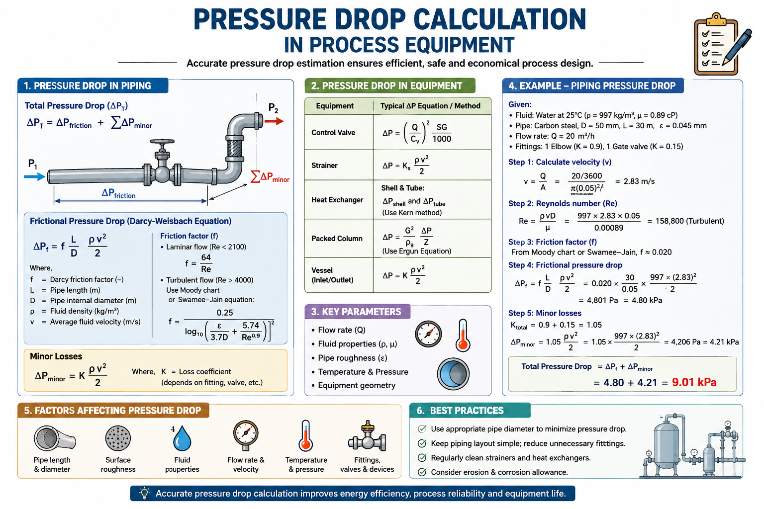
Pressure drop calculation is one of the most important aspects of process engineering and equipment design. Whenever a fluid flows through a pipe, valve, heat exchanger, filter, packed bed, reactor, or other process equipment, some pressure is lost because of friction, fittings, changes in flow direction, equipment resistance, and elevation differences.
Accurate pressure drop calculation in process equipment is essential for selecting pumps and compressors, determining pipe sizes, estimating operating costs, checking equipment performance, and ensuring stable plant operation.
This article explains the fundamentals of pressure drop, major calculation methods, important equations, and practical applications in chemical and process industries.
What Is Pressure Drop?
Pressure drop, represented by ΔP, is the difference between the pressure at the inlet and outlet of a process system.
ΔP=Pin−Pout
When a fluid flows through a process system, pressure decreases because energy is consumed overcoming hydraulic resistance.
The total pressure drop can be represented as:
ΔPtotal=ΔPpipe+ΔPfittings+ΔPvalves+ΔPequipment
Pressure drop is generally expressed in Pa, kPa, bar, kg/cm², or psi.
For liquid systems, pressure drop can also be converted into head loss:
HL=ρgΔP
where HL is head loss in meters.
Why Pressure Drop Calculation Is Important
Proper pressure drop calculation is critical during both process design and plant operation.
Incorrect pressure-drop estimation can result in:
- Oversized or undersized pumps
- Insufficient flow through equipment
- Excessive energy consumption
- Poor heat exchanger performance
- Valve operating problems
- High compressor power consumption
- Cavitation risk
- Inadequate equipment capacity
- Process instability
In chemical plants, pressure drop is particularly important because process fluids can have high viscosity, suspended solids, corrosive properties, or significant changes in density and temperature.
Pressure Drop in Straight Pipes
The most commonly used equation for calculating pressure loss in a straight pipe is the Darcy-Weisbach equation:
ΔP=fDL2ρv2
where:
- f = Darcy friction factor
- L = pipe length, m
- D = internal pipe diameter, m
- ρ = fluid density, kg/m³
- v = fluid velocity, m/s
The fluid velocity is calculated from:
v=AQ
For a circular pipe:
A=4πD2
Therefore:
v=πD24Q
The calculation shows that pipe diameter has a major influence on pressure drop. Reducing pipe diameter increases velocity and can significantly increase pressure loss.
Reynolds Number and Flow Regime
The Reynolds number is used to determine whether flow is laminar or turbulent.
Re=μρvD
where:
- ρ = fluid density
- v = velocity
- D = pipe diameter
- μ = dynamic viscosity
Typical flow classifications are:
| Reynolds Number | Flow Regime |
|---|---|
| < 2,300 | Laminar |
| 2,300–4,000 | Transitional |
| > 4,000 | Turbulent |
For laminar flow:
f=Re64
For turbulent flow, the friction factor depends on Reynolds number and pipe roughness.
The Colebrook equation is widely used:
f1=−2log10[3.7ϵ/D+Ref2.51]
where ϵ is the absolute roughness of the pipe.
Pressure Drop Through Valves and Fittings
Straight pipe friction is only one component of total pressure loss. Valves, elbows, tees, reducers, entrances, exits, and other fittings also create pressure losses.
The basic equation is:
ΔPminor=K2ρv2
where K is the dimensionless loss coefficient.
For multiple fittings:
ΔPfittings=∑K2ρv2
The total pipeline pressure drop can therefore be written as:
ΔP=(fDL+∑K)2ρv2
Typical fittings producing pressure losses include 90° elbows, tees, globe valves, control valves, reducers, strainers, and expansion sections.
Actual K values should preferably be obtained from reliable engineering references or equipment manufacturers.
Pressure Drop Calculation in Heat Exchangers
Heat exchanger pressure drop is an important design parameter because excessive pressure loss increases pumping requirements.
For a shell-and-tube heat exchanger, pressure drop is calculated separately for the tube and shell sides.
Tube-side pressure drop
Tube-side pressure drop depends on:
- Tube diameter
- Tube length
- Number of passes
- Fluid velocity
- Fluid density
- Fluid viscosity
- Tube roughness
- Return losses
A simplified calculation is:
ΔPt=[fDiLeffective+∑K]2ρv2
For the shell side, pressure drop depends on shell diameter, baffle spacing, baffle cut, tube arrangement, tube pitch, and fluid velocity.
For detailed shell-side calculations, established methods such as the Bell-Delaware method may be applied.
Pressure Drop in Plate Heat Exchangers
In plate heat exchangers, pressure loss depends strongly on plate geometry and operating conditions.
Important factors include:
- Chevron angle
- Channel velocity
- Number of plates
- Plate thickness
- Channel gap
- Fluid viscosity
- Fluid density
- Fouling
The total pressure drop can be considered as:
ΔPtotal=ΔPport+ΔPchannel+ΔPturn
For final equipment selection, manufacturer pressure-drop data is normally preferred.
Pressure Drop Across Filters
Filters and strainers can develop increasing pressure drop as solids accumulate.
The filter pressure drop can be expressed as:
ΔP=Pin−Pout
A clean filter generally has relatively low pressure drop. As the filter becomes loaded with solids, resistance increases.
Monitoring filter ΔP is therefore an important process equipment maintenance parameter.
High filter pressure drop can indicate:
- Filter blockage
- Excessive solids loading
- Incorrect filter selection
- Insufficient filtration area
- High fluid viscosity
Differential-pressure monitoring can help determine when cleaning or replacement is required.
Pressure Drop Across Packed Beds
Packed beds are commonly used in chemical processing, adsorption, gas absorption, catalysis, and filtration.
The Ergun equation is widely used for calculating packed-bed pressure drop:
LΔP=150ϵ3dp2μ(1−ϵ)2vs+1.75ϵ3dpρ(1−ϵ)vs2
where:
- ϵ = bed void fraction
- dp = particle diameter
- vs = superficial velocity
- L = packed-bed height
Pressure drop generally increases with increasing bed height and velocity, while smaller packing particles tend to produce higher resistance.
Pressure Drop in Gas Systems
Gas pressure drop calculation requires additional consideration because gases are compressible.
Important parameters include:
- Absolute pressure
- Temperature
- Gas molecular weight
- Compressibility factor
- Gas density
- Viscosity
- Pipe diameter
- Pipe roughness
- Gas velocity
For relatively small pressure changes, simplified calculations may sometimes be acceptable. However, significant pressure changes require appropriate compressible-flow pressure drop calculations.
Gas pressure-drop calculations are particularly important for natural gas, process gas, steam, air, nitrogen, hydrogen, and other industrial gases.
Pressure Drop Calculation Example
Consider a water pipeline with:
- Flow = 100 m³/h
- Pipe ID = 100 mm
- Pipe length = 100 m
- Density = 1,000 kg/m³
- Viscosity = 1 cP
Flow conversion:
Q=3600100=0.02778m3/s
Pipe area:
A=4π(0.1)2=0.007854m2
Velocity:
v=0.0078540.02778 v=3.54m/s
The Reynolds number is approximately:
Re=3.54×10⁵
indicating turbulent flow.
Assuming a Darcy friction factor of approximately 0.017:
ΔPpipe=0.0170.110021000(3.54)2
The straight-pipe pressure drop is approximately:
ΔPpipe≈1.07bar
If fittings contribute approximately 0.35 bar:
ΔPtotal=1.07+0.35 ΔPtotal≈1.42bar
This example demonstrates why both pipe friction and fitting losses must be considered in a complete hydraulic calculation.
Pressure Drop and Pump Selection
Pressure-drop calculation is directly connected with pump selection.
The pump must provide sufficient head to overcome:
- Static elevation
- Pipe friction
- Fitting losses
- Equipment pressure drop
- Control valve losses
- Required downstream pressure
A simplified pump-head relationship is:
Hpump=ρgΔPsystem+Δz
An accurate pump hydraulic calculation helps avoid selecting an unnecessarily large pump, which can increase capital and operating costs.
Pressure Drop in Chemical Process Plants
Pressure-drop calculations are especially important in chemical and fertilizer plants.
For example, in a phosphoric acid plant, hydraulic resistance may occur through:
- Acid pipelines
- Slurry pipelines
- Heat exchangers
- Filters
- Scrubbers
- Pumps
- Control valves
- Reactors
- Evaporators
- Cooling systems
Phosphoric acid and process slurries can have properties very different from water. Density, viscosity, solids concentration, temperature, scaling, and pipe lining must therefore be considered.
For slurry systems, simple water-based calculations may not provide reliable results. The designer should consider slurry rheology, particle size, settling velocity, pipe velocity, and erosion risk.
How to Reduce Pressure Drop in Process Equipment
Pressure drop can often be reduced by:
- Increasing pipe diameter
- Reducing unnecessary pipe length
- Minimizing sharp bends
- Using low-loss valves
- Optimizing equipment configuration
- Maintaining clean filters
- Controlling fouling
- Optimizing heat exchanger design
- Selecting suitable pump operating conditions
- Maintaining appropriate fluid velocity
However, reducing pressure drop should not be done blindly. Very low velocity in slurry lines, for example, can result in solids settling and pipeline blockage.
Conclusion
Pressure drop calculation in process equipment is a fundamental part of chemical and mechanical engineering design. The Darcy-Weisbach equation provides the basic approach for straight-pipe friction, while fitting losses are calculated using loss coefficients. Heat exchangers, filters, packed beds, valves, and other equipment require specialized pressure-drop methods.
A reliable hydraulic calculation should consider the complete flow path rather than only the straight pipe. Fluid properties, velocity, pipe diameter, roughness, fittings, equipment resistance, elevation, fouling, and operating conditions all influence the final pressure drop.
For chemical process plants, accurate pressure-drop calculations help engineers optimize pump selection, energy consumption, equipment sizing, process reliability, and plant performance. Proper hydraulic design ultimately contributes to safer, more efficient, and more economical process operation.