
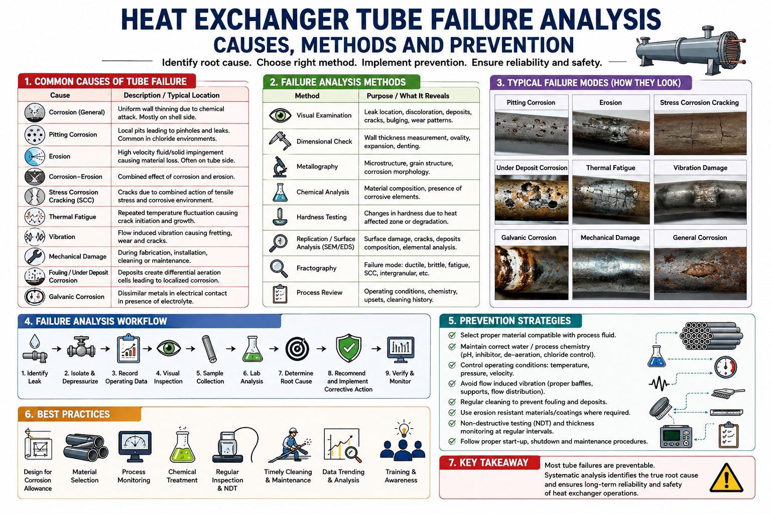
Heat exchangers are critical process equipment in chemical, petrochemical, fertilizer, refinery, power, pharmaceutical, and food-processing industries. Among the various failure modes of heat exchangers, tube failure is one of the most common and potentially serious problems.
A failed heat exchanger tube can cause process-fluid contamination, product loss, pressure imbalance, equipment shutdown, corrosion damage, safety hazards, and expensive maintenance. Therefore, heat exchanger tube failure analysis is an important part of equipment reliability and preventive maintenance.
This article explains the major causes of tube failure, inspection methods, failure mechanisms, root-cause analysis, and preventive measures.
What Is Heat Exchanger Tube Failure?
Heat exchanger tube failure occurs when a tube develops a defect that prevents it from safely containing the process fluid.
Typical defects include:
- Tube leakage
- Tube-wall thinning
- Pitting
- Cracking
- Erosion
- Corrosion
- Tube rupture
- Tube-end leakage
- Vibration damage
- Fretting
- Stress corrosion cracking
- Mechanical deformation
Tube failure can occur suddenly or develop gradually over months or years.
Why Heat Exchanger Tubes Fail
Heat exchanger tubes operate under a combination of:
- Pressure
- Temperature
- Fluid velocity
- Thermal cycling
- Chemical attack
- Mechanical vibration
- Differential expansion
- Fouling
- Flow-induced forces
The failure mechanism is therefore rarely caused by a single parameter. In many cases, material selection, process chemistry, operating conditions, fabrication quality, and maintenance practices interact to produce tube damage.
1. Corrosion
Corrosion is one of the most common causes of heat exchanger tube failure.
It occurs when the tube material reacts chemically or electrochemically with the process fluid.
Common forms include:
General corrosion
Uniform reduction in tube-wall thickness occurs over a large surface area.
Pitting corrosion
Localized corrosion creates small but deep cavities.
Pitting can be particularly dangerous because a tube may appear acceptable externally while having severe localized penetration.
Crevice corrosion
This occurs in stagnant or shielded areas such as:
- Tube-to-tubesheet joints
- Gaskets
- Deposits
- Tube supports
- Lap joints
Galvanic corrosion
Galvanic corrosion occurs when dissimilar metals are electrically connected in the presence of an electrolyte.
2. Erosion-Corrosion
High fluid velocity can mechanically remove the protective film from a tube surface.
The combination of mechanical erosion and chemical corrosion is called erosion-corrosion.
It is commonly observed near:
- Tube entrances
- Elbows
- Bends
- Inlet nozzles
- Areas of flow acceleration
Typical symptoms include localized wall thinning and characteristic grooves or attack patterns.
Increasing velocity does not always improve heat exchanger performance because excessive velocity can accelerate tube damage.
3. Flow-Induced Vibration
Heat exchanger tubes can vibrate because of:
- High shell-side velocity
- Turbulence
- Vortex shedding
- Two-phase flow
- Poor tube support
- Improper baffle spacing
Continuous vibration can cause:
- Tube-to-tube contact
- Fretting
- Fatigue cracking
- Wear at supports
- Tube rupture
Flow-induced vibration is particularly important in shell-and-tube heat exchangers.
Tube vibration should therefore be considered during the original exchanger design as well as during failure investigation.
4. Thermal Fatigue
Repeated temperature changes cause repeated expansion and contraction of the tube material.
If the thermal stresses exceed the material’s fatigue resistance over sufficient cycles, cracks can develop.
Thermal fatigue can occur during:
- Startup
- Shutdown
- Emergency trips
- Steam admission
- Cold-water introduction
- Sudden process changes
Repeated thermal cycling can eventually produce fatigue cracks, particularly at locations containing stress concentrations.
5. Stress Corrosion Cracking
Stress corrosion cracking (SCC) occurs when three conditions are present:
- Susceptible material
- Aggressive environment
- Tensile stress
The resulting cracks can propagate rapidly and may cause sudden tube leakage.
Potentially susceptible materials and environments depend strongly on alloy and process chemistry. Chloride-containing environments, for example, can be problematic for certain stainless steels.
6. Tube Sheet and Tube Joint Failure
Not every exchanger leak originates from the tube body.
Leaks can also develop at the:
- Tube-to-tubesheet joint
- Expanded joint
- Welded joint
- Tube end
- Tube sheet
Common causes include:
- Improper tube expansion
- Incorrect rolling
- Poor welding
- Differential thermal expansion
- Corrosion
- Mechanical damage
- Excessive vibration
During inspection, the tube body and tube-to-tubesheet connection should therefore be evaluated separately.
7. Fretting Wear
Fretting occurs when small-amplitude relative movement takes place between contacting surfaces.
In heat exchangers, tube vibration against supports or baffles can produce localized wear.
Typical characteristics include:
- Localized tube-wall thinning
- Polished contact areas
- Grooves
- Oxide/debris formation
- Progressive leakage
Fretting damage is often associated with inadequate tube support or excessive vibration.
8. Fouling-Related Tube Failure
Fouling can indirectly contribute to tube failure.
Deposits may:
- Reduce heat transfer
- Increase pressure drop
- Create under-deposit corrosion
- Restrict flow
- Produce localized overheating
- Promote microbiological activity
For example, a deposit layer can create a localized environment beneath the deposit where corrosion becomes much more aggressive than on the clean tube surface.
Heat Exchanger Tube Failure Analysis Procedure
A systematic failure investigation should follow a structured approach.
Step 1: Collect Operating History
Gather:
- Design pressure
- Design temperature
- Operating pressure
- Operating temperature
- Fluid composition
- Flow rate
- Previous failures
- Cleaning history
- Shutdown history
- Water chemistry
- Chemical dosing records
The objective is to determine whether operating conditions changed before the failure.
Step 2: Identify the Failure Location
Determine exactly where the damage occurred.
Ask:
- Is it on the tube inlet?
- Tube outlet?
- Tube middle?
- Near a baffle?
- Near the tubesheet?
- At the tube-to-tubesheet joint?
Failure location often provides an important clue regarding the mechanism.
Step 3: Visual Inspection
Perform visual examination of the failed tube.
Look for:
- Pits
- Cracks
- Grooves
- Deposits
- Discoloration
- Deformation
- Erosion marks
- Fretting marks
Photographs should be taken before cleaning the damaged surface.
4. Non-Destructive Testing
Several heat exchanger tube inspection methods are available.
Eddy Current Testing
Eddy current testing is widely used for non-ferromagnetic heat exchanger tubes.
It can identify:
- Cracks
- Pitting
- Wall thinning
- Corrosion
- Localized defects
Remote Field Testing
Remote field techniques are useful for inspection of ferromagnetic tubes.
Ultrasonic Testing
Ultrasonic testing can determine:
- Remaining wall thickness
- Localized thinning
- Pitting depth
- Cracks in suitable applications
Hydrostatic Testing
Hydrotesting can identify leakage but may not reveal the complete nature of an existing defect.
Dye Penetrant Testing
Dye penetrant testing is useful for detecting surface-breaking cracks on suitable accessible surfaces.
5. Destructive Testing and Laboratory Analysis
When required, a failed tube sample should be removed for detailed laboratory investigation.
Important tests include:
Chemical Composition Analysis
Confirms whether the tube material matches the specified alloy.
Metallography
Metallographic examination can identify:
- Grain structure
- Corrosion morphology
- Cracking
- Heat treatment condition
- Metallurgical abnormalities
Hardness Testing
Abnormal hardness can indicate material or manufacturing problems.
Scanning Electron Microscopy
SEM can provide detailed information about fracture surfaces and crack morphology.
Energy Dispersive X-ray Analysis
EDS can help identify elements present in deposits and corrosion products.
Root Cause Analysis of Tube Failure
Finding the immediate failure mechanism is not always enough.
For example:
Observation: Tube has a through-wall pit.
Failure mechanism: Pitting corrosion.
But the root cause may be:
- High chloride concentration
- Incorrect material selection
- Poor water chemistry control
- Deposit accumulation
- Inadequate corrosion monitoring
A useful failure investigation therefore separates:
Symptom → Failure mechanism → Contributing factors → Root cause → Corrective action
Techniques such as 5 Why analysis, Fishbone diagrams, Fault Tree Analysis, and Root Cause Analysis (RCA) can be used.
Common Heat Exchanger Tube Failure Mechanisms
| Failure mechanism | Typical appearance | Common cause |
|---|---|---|
| General corrosion | Uniform thinning | Aggressive fluid |
| Pitting | Deep localized holes | Chlorides/deposits |
| Erosion | Grooves/thinning | High velocity |
| Erosion-corrosion | Localized thinning | Velocity + corrosion |
| Fretting | Grooves near supports | Tube vibration |
| Fatigue | Cracks | Cyclic stress |
| Thermal fatigue | Cracks | Temperature cycling |
| SCC | Fine cracks | Stress + environment |
| Vibration damage | Wear/cracks | Poor tube support |
| Joint leakage | Leakage at tubesheet | Poor expansion/welding |
| Fouling | Deposit layer | Contamination/poor treatment |
How to Prevent Heat Exchanger Tube Failure
Effective prevention begins with proper design.
Material Selection
Tube material should be selected according to:
- Fluid chemistry
- Temperature
- Pressure
- Chloride concentration
- pH
- Corrosion potential
- Erosion risk
Control Fluid Velocity
Velocity should remain within the recommended design range for the selected material and service.
Water Chemistry Control
For cooling-water systems, monitor:
- pH
- Chlorides
- Conductivity
- Hardness
- Dissolved oxygen
- Microbiological activity
Fouling Control
Regular cleaning and proper chemical treatment can minimize deposit formation.
Vibration Control
Tube support and baffle design should minimize excessive tube vibration.
Regular Inspection
Develop an inspection program using:
- Eddy current testing
- Ultrasonic thickness measurement
- Visual inspection
- Pressure testing
- Tube leak detection
Heat Exchanger Tube Failure: Practical Troubleshooting
When repeated tube failures occur, simply plugging the failed tubes may not solve the problem.
A proper investigation should examine:
- Where is the failure occurring?
- Which side of the exchanger is responsible?
- What is the tube material?
- Has process chemistry changed?
- Has flow velocity increased?
- Are deposits present?
- Is tube vibration occurring?
- Are failures concentrated near baffles or tubesheets?
- Has the exchanger experienced frequent thermal cycling?
- Are similar exchangers showing the same problem?
The failure pattern is often more valuable than examination of a single damaged tube.
Conclusion
Heat exchanger tube failure analysis is essential for maintaining process reliability and preventing unexpected shutdowns. Tube failures can result from corrosion, erosion, vibration, fatigue, stress corrosion cracking, fouling, poor tube support, thermal cycling, and tube-to-tubesheet joint problems.
A successful investigation should combine operating-history analysis, visual inspection, non-destructive testing, metallurgical examination, fluid analysis, and root-cause analysis.
The objective should not simply be to identify the failed tube. The real objective is to determine why the tube failed and how to prevent recurrence.
For chemical and process industries, a proactive tube inspection and condition-monitoring program can significantly improve heat exchanger reliability, reduce maintenance costs, minimize product contamination, and extend equipment service life.